Hardware Appliance Overview
You have obtained the Hardware Appliance from Keyfactor.
In the following sections, you will find information about the scope of delivery as well as details about the Hardware Appliance device.
Scope of Delivery
The Hardware Appliance package contains the following items:
| 1 Quality Assurance Test Report | The Hardware Appliance Test Report lists the quality checks that have been performed. It is signed by Keyfactor authorized personnel. |
| 1 Packing List | |
| 1 Hardware Appliance |
|
| 1 External Battery Adapter (standard 6LR61/9 Volt block battery is not supplied) Pictures show the front and the back side. |
 |
| 1 Set of mounting rails with a mounting instruction and a set of screws | |
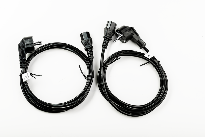
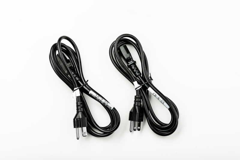
| 4 Mains cables, one pair each for European and American standard |
|
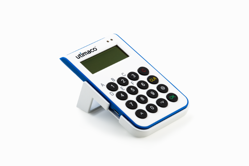
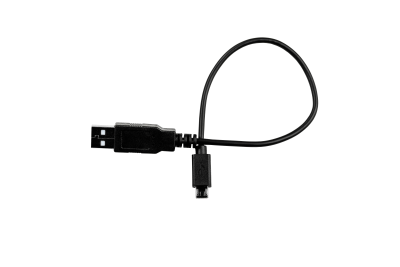
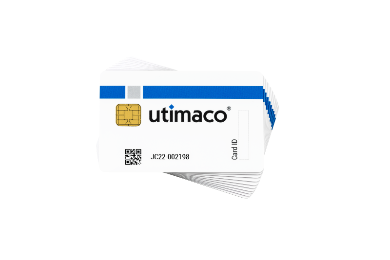
| 1 Smart Card Reader with PIN pad and display cable (optional) 10 smart cards |
|
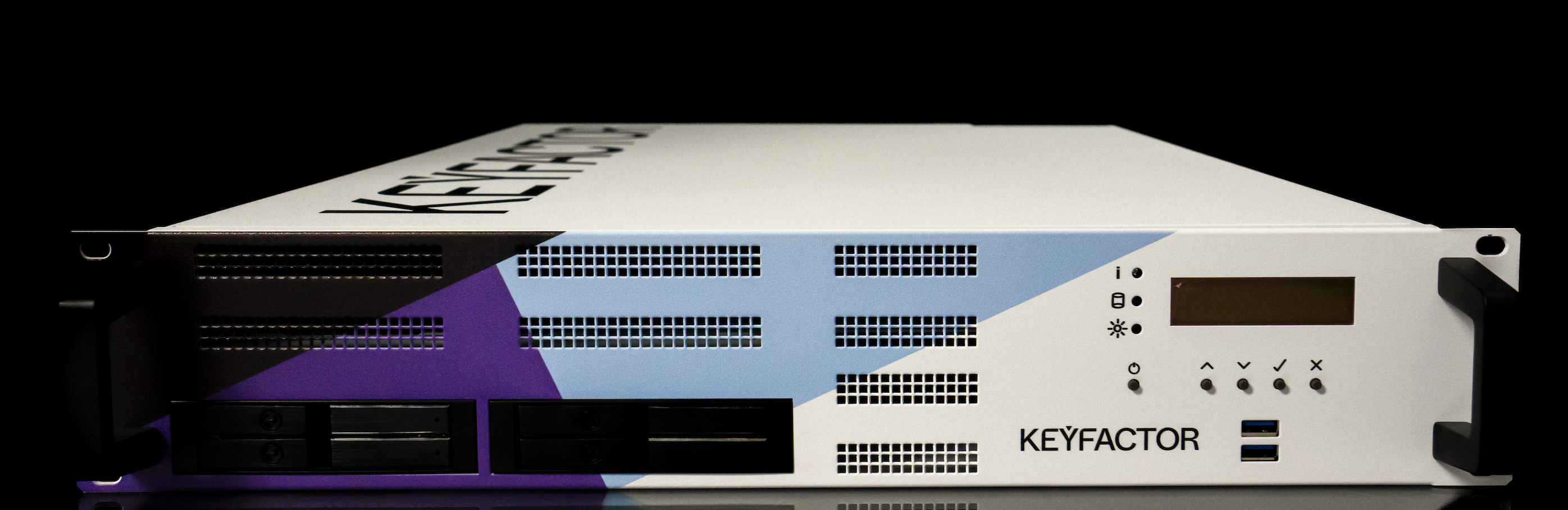
Overview - Front Hardware Version 2
The following illustrates the front view of the Hardware Appliance.
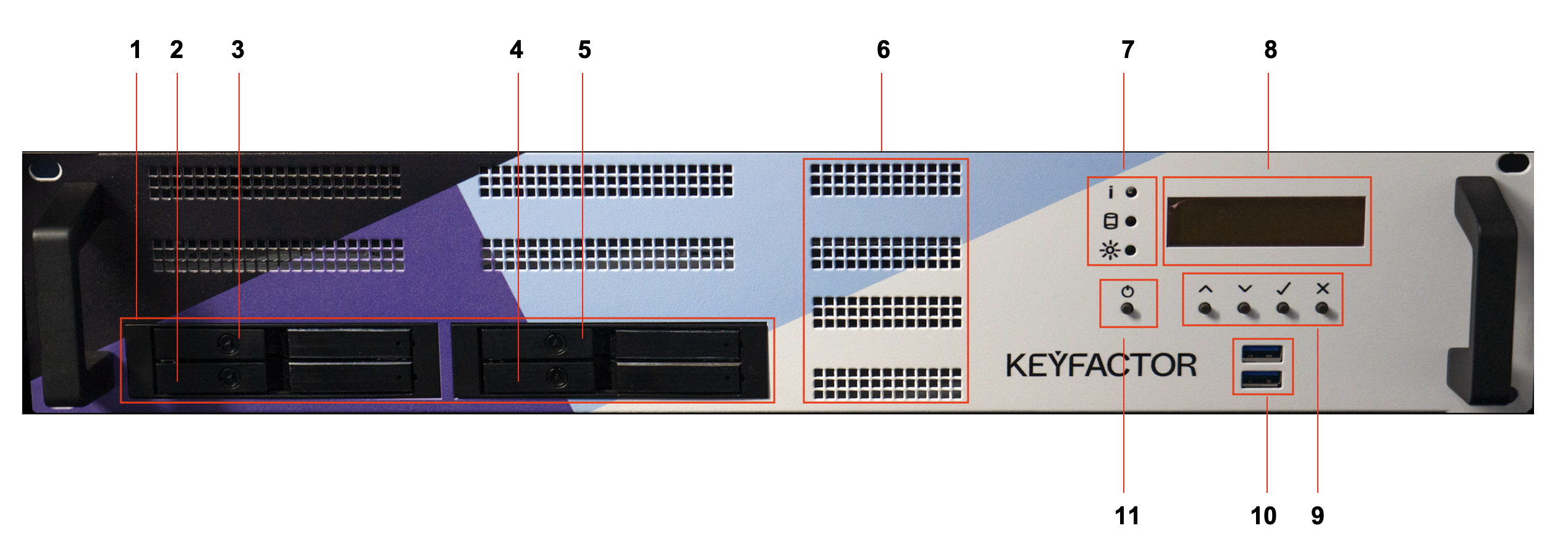
- Four bays for customer serviceable hard disks, (Solid State Disks (SSD)) for database and RAID1.
Two disks are provided, two bays are empty. - SSD Slot 0
- SSD Slot 1
- SSD Slot 2, empty
- SSD Slot 3, empty
- Cooling vents:
Do not obstruct the vents. - Status LED row:
Green: Power
Red: Hard Disk
Yellow: Info - Front display for status information and IP address configuration messages
- Menu buttons to operate the front display:
Up, Down, Enter, Cancel - Front USB ports:
The ports are suitable for PIN pad connection. - Power button, ATX power supply
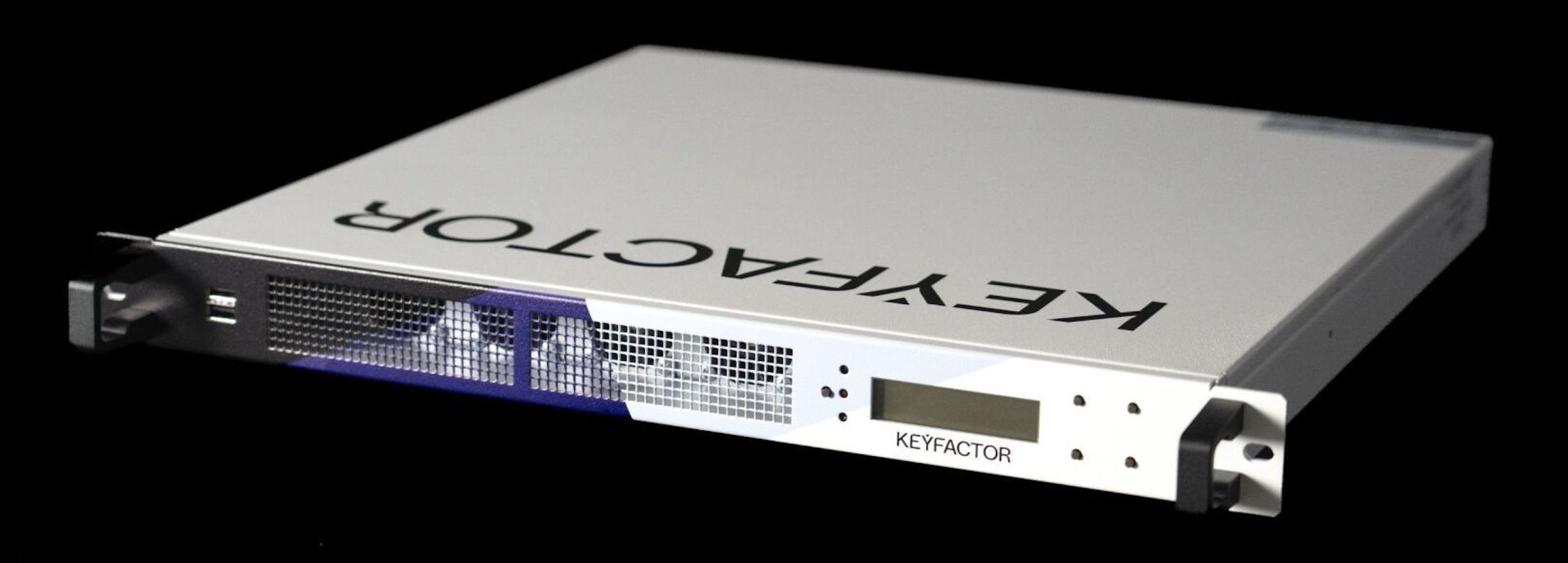
Overview - Front Hardware Version 4
The following illustrates the front view of the Next Generation Hardware Appliance.
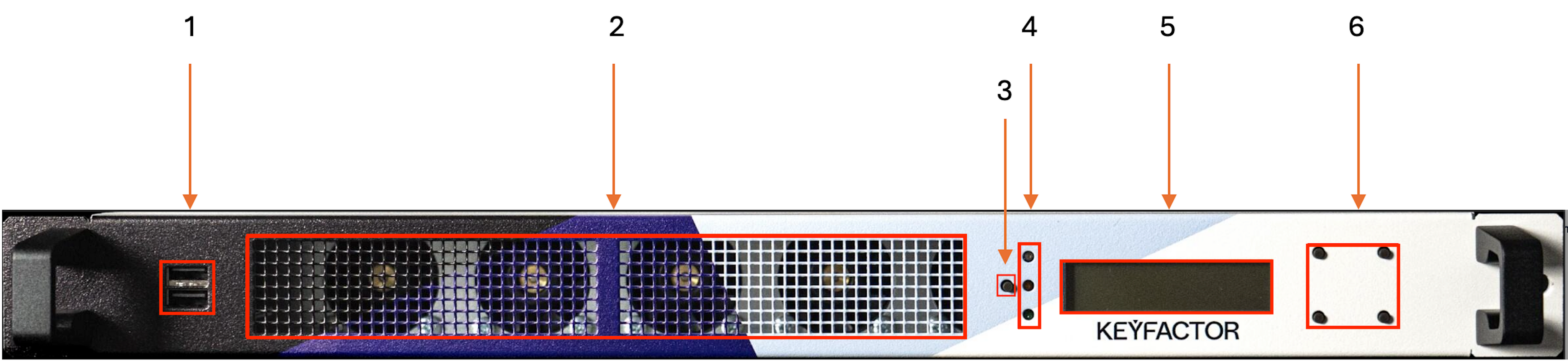
Front USB ports:
The ports are suitable for PinPad connection.Cooling vents:
Do not obstruct the vents.Power
Status LED row:
Green: Power
Red: Hard Disk
Yellow: InfoFront display for status information and IP address configuration messages
Menu buttons to operate the front display:
start from left on top row
Up, Down, Enter, Cancel
Overview - Back Hardware Version 2
The following illustrates the back view of the Hardware Appliance.
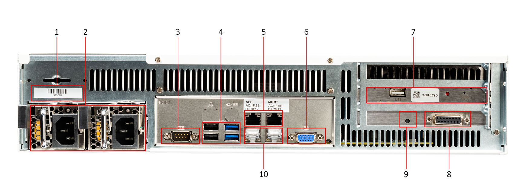
- Hardware Appliance serial number
- Two power supply units (PSU), redundant
- Mainboard serial connection, not operational
- Mainboard USB ports, suitable for PIN pad connection
- Application network interface (left) and Management network interface (right)
- Mainboard VGA connector, not required for operation
- Hardware Security Module (HSM)
Do not use the USB port or the buttons! Connector for external battery and test automation
- Safeguarded External Erase button for Factory Reset
- Additional network interfaces, currently not activated
Overview - Back Hardware Version 4
The following illustrates the back view of the Next Generation Hardware Appliance.
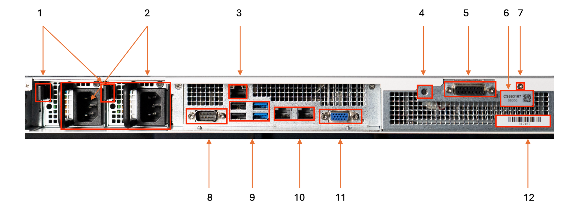
Hot plug release button for Power Supply Unit (PSU)
Two power supply units (PSU), redundant
Ethernet Port
Safeguarded External Erase button for Factory Reset
Connector for external battery and test automation
HSM serial number
LED from HSM
Mainboard serial connection, not operational
Mainboard USB ports, suitable for PIN pad connection
Application network interface (left) and Management network interface (right)
Mainboard VGA connector, not required for operation
Keyfactor Next Generation Hardware Appliance serial number
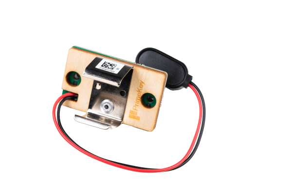
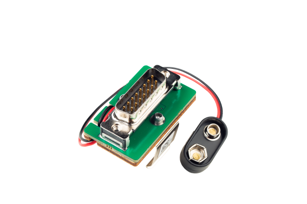
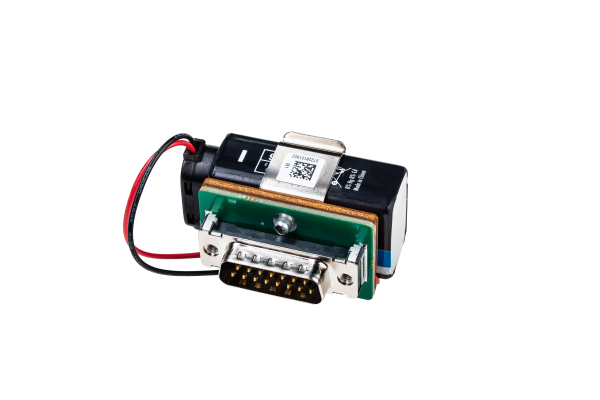
External Battery Adapter
The following illustrates the external battery adapter of the Hardware Appliance.
| Side to be plugged into the device |
|
| Side that holds the battery |
|
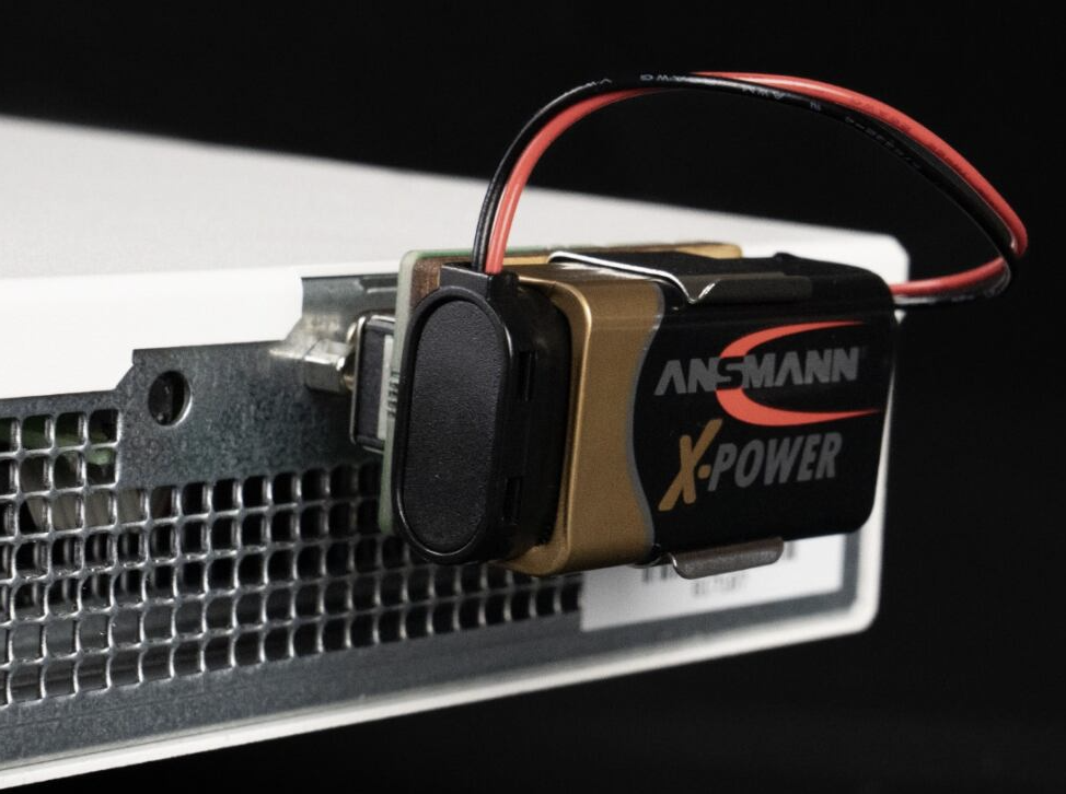
| External battery adapter with connected battery |
|
| Connected external battery adapter | Hardware Version 2 |
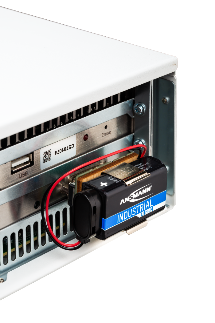
The external battery adapter has the task to support the power supply of the HSM. The HSM always requires power, even when the Hardware Appliance has not been put into operation or is not supplied with power. The HSM's internal battery is not designed to be inactive for extended periods of time. To prevent the HSM from being fully discharged and thus placed in maintenance mode, use the external battery adapter to buffer the internal HSM battery and extend its lifetime when the Hardware Appliance is powered off. This is useful, for example, when a Hardware Appliance is operated as an offline (root) CA.
Preparation and Checks for Commissioning / Powering Up
Note the following when taking the Hardware Appliance into operation and powering it up.
- Make sure the seal at the right side of the Hardware Appliance is intact and has not been tampered with.
- Make sure the serviceable hard disks are sitting properly in their bay.
- Make sure the PSUs sit properly.
- Connect the power cord.
Connect the network cables.

Important!
Both network cables must be plugged in and connected to the network before starting the Hardware Appliance.
Provide the External Battery Adapter with batteries and connect it.

The External Battery Adapter should already be fitted with a battery and running if the Hardware Appliance is not installed immediately upon delivery.
Important!
It is important that the External Battery Adapter is constantly in operation.
Power on the machine to start booting. Booting will take about 5 minutes.
Default IP address
The default IP addresses used by the Hardware Appliance are 192.168.5.160 and 192.168.5.161. If these IP addresses are already in use on your network, this will cause an IP address conflict.